One workflow
From settings fileto filed report
A worked example, in the order it actually happens. Every result on this page came from the built-in simulator. The bounded OMICRON path in the shipping build is not represented by these screenshots or qualified as equivalent evidence.
The shape of the job
Seven steps, one record at the end
The application is built around the idea that testing and documenting are one task that people have been forced to do twice.
A test session starts from settings and ends as a record attached to an asset. In between, the plan is explicit, the expected values are computed rather than typed, and each measured point carries its own verdict. Nothing about that requires the copilot; the copilot just removes the typing.
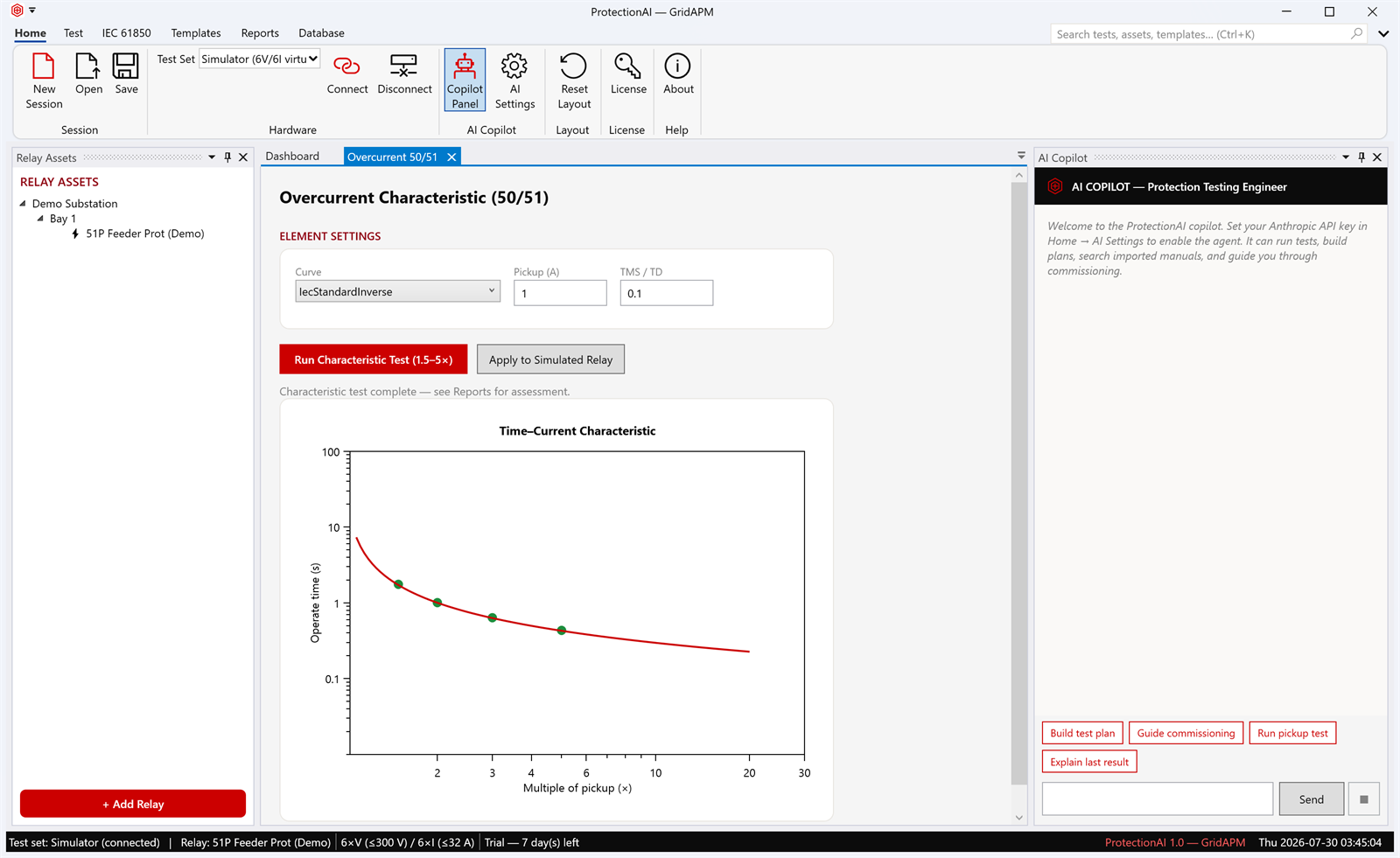
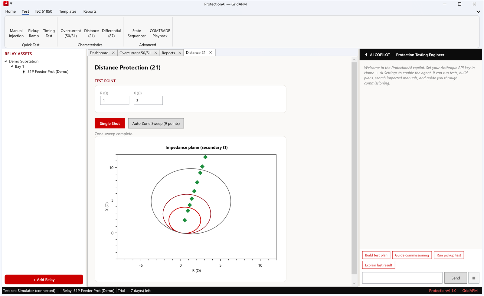
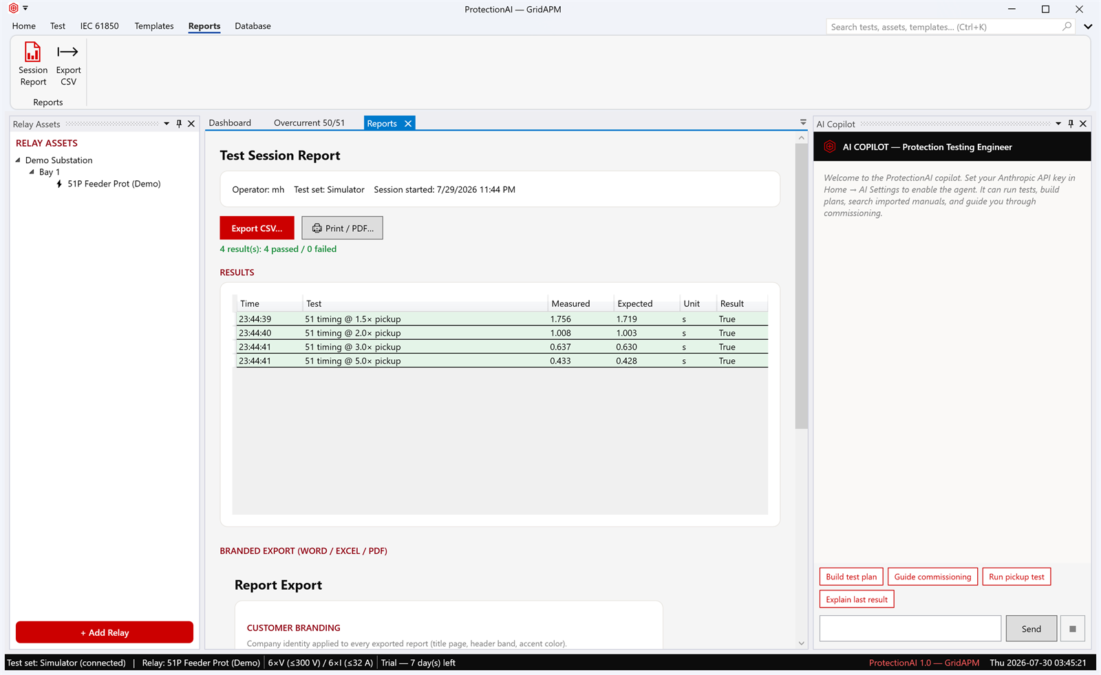
What follows is the overcurrent example captured in the screenshots below: an IEC standard-inverse element with a 1 A pickup and a time multiplier of 0.1, tested at four multiples of pickup, then a nine-point distance zone sweep on the same relay.
Step 3
A completed 50/51 characteristic
The workflow
Import, plan, run, review, sign, export, file
Each step is a place you can stop, disagree and change something.
-
Import the settings
Bring in the relay's parameters from an OMICRON XRIO or RIO file, or from a JSON template, or type them. Import lands in one normalised settings model, so a curve type, a pickup and a time multiplier mean the same thing to every module regardless of how they arrived.
-
Build or generate the plan
Assemble the test plan by choosing modules and their test points — the multiples of pickup for a 50/51 sweep, the line and point count for a distance sweep, the state durations for a sequence. Or hand the imported settings and the relay manual to the copilot and let it draft the plan for you to correct.
-
Run it against the simulator
Execute the plan against the built-in simulator: a virtual test set and a configurable simulated relay with realistic contact timing. The status bar and the report header both name the test set, so nobody downstream mistakes a rehearsal for a hardware result. The bounded OMICRON adapter and the generic SCPI source can also be selected; neither is hardware-in-the-loop qualified, and each states its limits.
-
Review measured against expected
Each point is captured with its measured value, the expected value computed from the standard's equation, the tolerance applied and a pass or fail verdict. The plots put the measured points on the same axes as the expected characteristic, which is usually where a wrong time multiplier or a swapped CT ratio becomes obvious.
-
Sign off
Record the operator and accept the session. A failed point stays a failed point; the workflow does not offer to make it disappear, and the verdict column is the reason the record is worth keeping.
-
Export the branded report
Generate the report in Word, Excel or PDF carrying your own logo and identity, or export CSV if the destination is a spreadsheet. The measured-against-expected table and the per-row verdicts travel with it.
-
File it against the asset
Store the session as a test record against the relay asset in the local database, alongside the settings version it was run on and any attachments. Next year's as-found comparison starts from that record rather than from a search of somebody's mailbox.
Step 4
A nine-point zone sweep
The verdict column
Expected values are computed, not remembered
For an inverse-time element, the expected operate time at each multiple of pickup is evaluated from the IEC 60255-151 or IEEE C37.112 equation for the selected characteristic, with the configured time multiplier. For a distance element, the expected boundary is the configured zone reach and angle on the R–X plane. For a transformer differential, the module states its assessment basis on the page: results are judged to ±5% with reference to IEC 60255-187-1 and IEEE C37.91.
That matters for a practical reason. When expected values are computed from the settings and the standard, changing a setting changes the expectation, and a stale reference value cannot quietly pass a relay that has been re-configured since the last visit.
Step 6
The session report
The copilot
The approval loop
The copilot is an agent with tools, a central isolation gate for energizing actions, and deterministic verdicts.
Ask it to test the standard-inverse element on the relay you have open and it will propose the steps: read the working settings, choose the multiples of pickup, configure the module, run the sweep, read back the results, draft the report section. Anything with a consequence — writing to the settings model, driving outputs, starting a run, generating a file — is presented for your approval before it executes. You can approve it, change it or do that step yourself.
The copilot's knowledge of a specific relay comes from the PDF manuals you ingest into the application, searched locally, plus the settings model already loaded. It does not have a private line to your relay: it uses the same modules and the same settings model you do, which is why every result it produces lands in the same measured-against-expected structure as a hand-driven test.
If you never configure an API key, the panel stays inert. The full workflow above is a manual workflow; the copilot is an accelerator on top of it, not a dependency inside it.
The other GridAPM product
GridAPM also builds AgenticGrid Pro
AgenticGrid Pro
A local-first transformer APM workbench: diagnostic evidence in, an engineer-signed work package out.
Try it for seven days and check the claims yourself
Install ProtectionAI on a Windows machine, import your own XRIO or RIO settings, run the plans you would really run against the built-in simulator and export a report on your own letterhead. No key is needed for the trial, and no internet connection is needed to run it. When you want a per-computer licence, email sales@gridapm.com.