Test modules
What ProtectionAI cantest today
102 modules across 17 ribbon tabs, grouped by protection family and ANSI device number, all qualified against the built-in simulator. The status table at the foot of this page says plainly what is implemented, what is partial and what is not built.
How it is organised
Modules grouped by family, not by menu depth
The ribbon follows the way protection work is actually divided up, so a distance engineer and a distribution engineer both find their own tools first.
Modules are arranged across the distance, differential, machine, line, distribution, commissioning and emerging protection families, and within each family by ANSI device number. 102 of them are registered in the version 1.10.0 build, spread over 17 ribbon tabs. All of them are qualified against the built-in simulator, which presents a virtual test set and a configurable simulated relay with realistic contact timing; the bounded OMICRON CM Engine adapter and the generic SCPI source driver can also be selected, each stating its limits, and neither is hardware-in-the-loop qualified.
The shared machinery underneath matters more than the module count. Every module writes into the same result model — measured value, expected value, tolerance, verdict — and every module reads from the same normalised settings model, whether those settings arrived by XRIO import, RIO import, JSON template or hand entry. That is why a session report can span four modules and still read as one document.
Navigation
The Protection ribbon
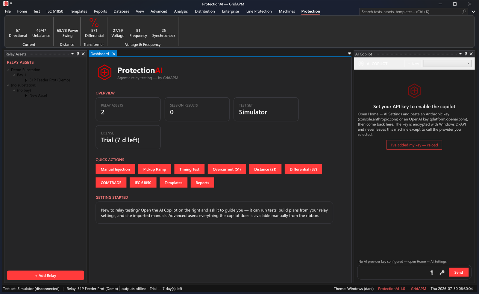
Current, voltage and frequency
Overcurrent and the voltage-derived elements
- Overcurrent (50/51)
- Full I–t characteristic sweeps: pick a set of multiples of pickup, let the module inject each one, capture the operate time and plot the measured points against the expected curve on log–log axes. Expected times come from the IEC 60255-151 or IEEE C37.112 equation for the selected characteristic and time multiplier.
- Pickup and dropout ramps
- Linear ramps on magnitude, with the reset ratio calculated from the measured pickup and dropout pair rather than assumed from the setting sheet.
- Voltage and frequency families
- Undervoltage and overvoltage (27 and 59), V/Hz (24), directional power (32) and voltage-controlled overcurrent (51V) have dedicated modules, and dedicated autoreclose (79), synchrocheck (25) and frequency and df/dt (81) modules ship alongside them, driven by the simulator's autoreclose scheme and rotating time base. The status table below states each one's limits.
- Directional and unbalance elements
- Directional overcurrent (67) and negative-sequence or phase-unbalance (46 and 47) appear in the Current group of the ribbon. Directional and sequence-element variants of the full 50/51 characteristic sweep are roadmap items rather than finished modules.
Impedance and differential
Distance and differential characteristics
- Distance (21)
- Automatic mho zone boundary search in the R–X plane. Choose a test line through the characteristic, set the number of points, and the module searches for the boundary crossing on each and plots the found points against the nested zone shapes on the secondary-ohm plane. A quadrilateral zone editor ships alongside it, with per-loop injection and k0 compensation; on the built-in simulator only the three-phase loop presents the target impedance, and the module states that per loop.
- Differential (87)
- Operate-point search across the bias and differential plane, so the measured characteristic is discovered rather than assumed, and then compared against the configured slopes.
- Transformer differential (87T)
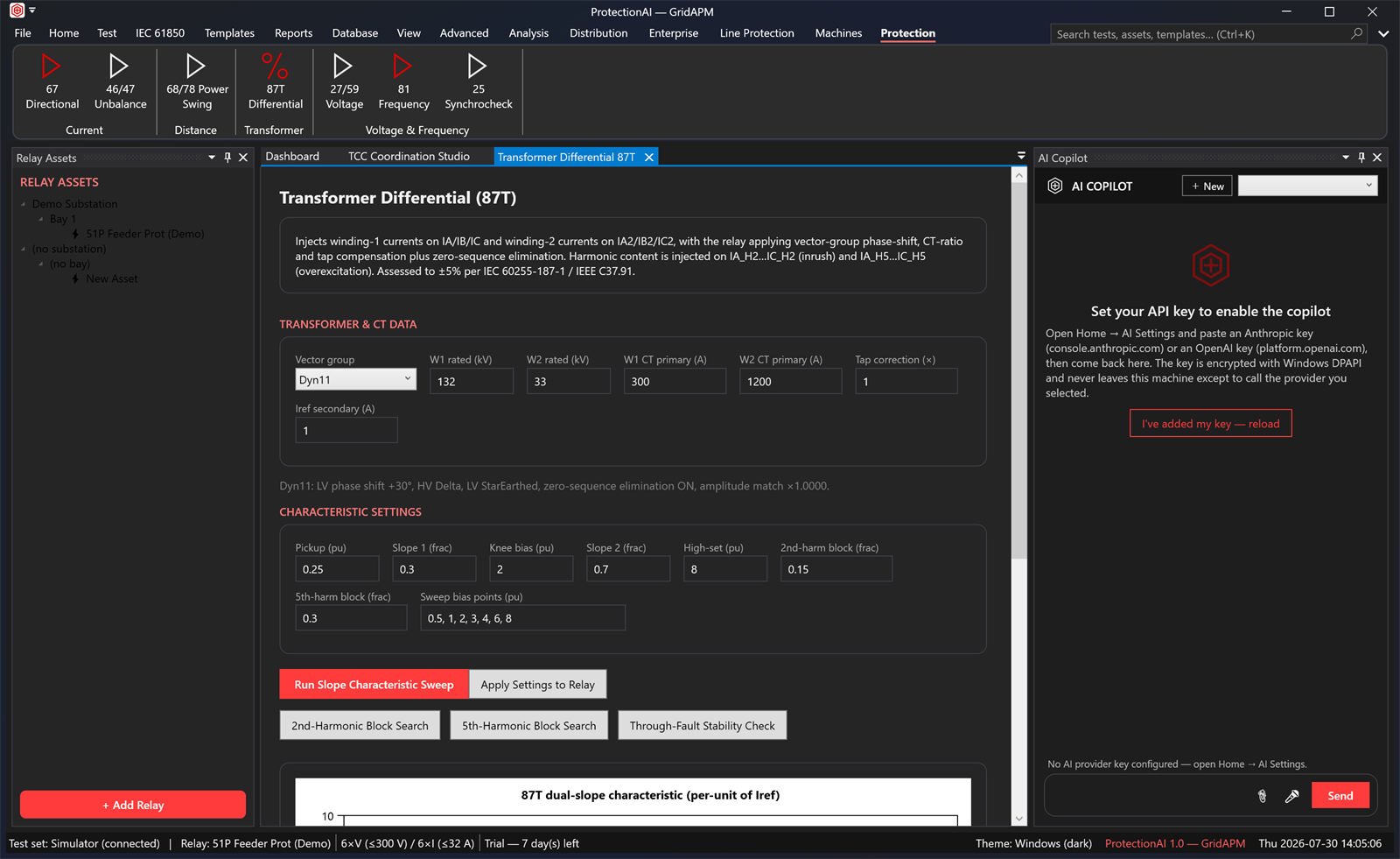
- Vector-group aware configuration — the capture shown below is a Dyn11 132/33 kV transformer — with dual-slope settings, a knee, a high-set element and second and fifth-harmonic block thresholds. Harmonic-restraint block searches and trip-time characteristic tests ship; the simulated harmonic block is magnitude-only, so a harmonic-phase sweep demonstrates invariance rather than phase-sensitive restraint.
- Machine protection
- The machine family covers the generator-side elements grouped in the ribbon. As with every family, read the status table rather than inferring coverage from the group heading.
87T
Transformer differential, configured
Line and distribution
Feeder coordination and line work
- TCC Coordination Studio
- A time–current coordination workspace that holds fuse links, recloser fast and slow curves, feeder relay elements and transformer damage curves on one set of axes. The plotted characteristics are computed from the entered settings by the module's standards-based models, not traced from a vendor catalogue image.
- Distribution devices
- Fuse bands are modelled from ANSI K-link data; transformer damage curves from IEEE C57.109; cable damage from IEC 60949. Relay characteristics use the IEC 60255-151 and IEEE C37.112 equations, the same mathematics the 50/51 module uses, so a coordination study and a timing test agree with each other.
- Emerging protection family
- A group for the elements that arrive with inverter-based resources and changing network behaviour: IBR and DER interconnection work referenced to IEEE 1547 and IEEE 2800, ROCOF and vector-shift anti-islanding, adaptive setting-group switching, arc-furnace harmonic discrimination, cold-load pickup and inrush restraint, broken conductor (46BC), subsynchronous resonance and loss-of-mains transfer-trip timing. Traveling-wave and time-domain testing at signal level remains at research stage and is not part of it.
- Commissioning family
- As-found and as-left settings verification that passes only when there are no unjustified changes and every restoration item is confirmed; a settings diff that never reports identical unless the comparison was genuinely like for like, and always states how many parameters it compared; an importer for the legacy Excel and CSV test sheets a team already has, with remembered column mappings; a report attachment bundle where images are appended as real PDF pages so they print; a PRC-005 R3 evidence assistant with completeness scoring; and an offline job pack you export, work from on site and merge back with a conflict report.
Dynamic and transient
Sequencer, COMTRADE playback and analysis
- Multi-state sequencer
- Define prefault, fault and postfault states with their own phasors and durations, declare the binary transitions you expect at each boundary, and the run is judged on whether the relay actually made those transitions in the window allowed.
- COMTRADE (IEEE C37.111)
- Open a record, inspect analog and digital channels on interactive plots, and play it back through the driver layer. Playback today terminates at the simulator rather than at an amplifier.
- Power-system simulation
- A network model you draw in a single-line editor using conventional IEC symbols, solved by a symmetrical-component short-circuit engine — three-phase, phase-phase, phase-ground and phase-phase-ground faults with fault resistance, returning per-phase and sequence quantities, all six distance loops with k0 compensation, and the source-to-impedance ratio. The solver is unit-tested against hand-computed reference cases. A scenario library sits alongside it.
- Transients and closed-loop playback
- Generated transients carry DC offset with X/R decay, CT saturation computed by flux integration from knee point, burden and remanence, CVT subsidence, evolving faults and inrush. Playback runs closed-loop: the breaker opens at the next current zero after the contacts part and the simulation continues from there, so autoreclose and breaker-failure sequences play out rather than being asserted.
- Charting and analysis
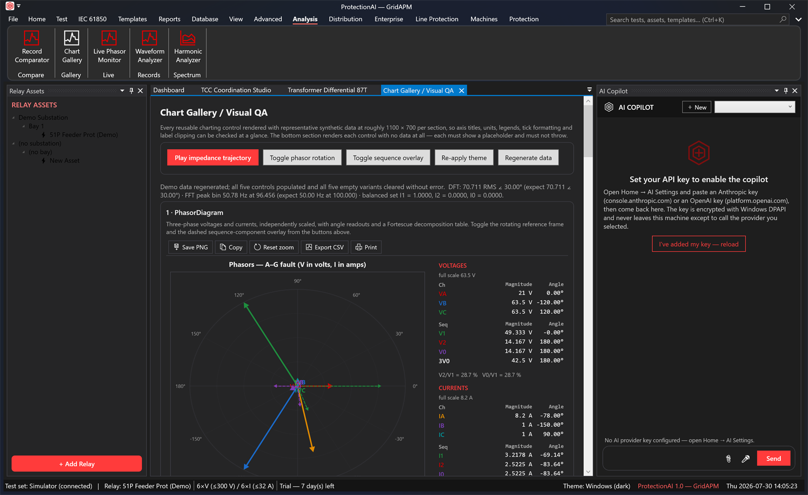
- Phasor diagrams, per-channel magnitude and angle tables and Fortescue sequence decomposition, plus the log–log and R–X plots the test modules write into.
Analysis
The charting library
Records
Asset and settings database
A local SQLite database, on your machine, with no service to stand up.
- Asset register
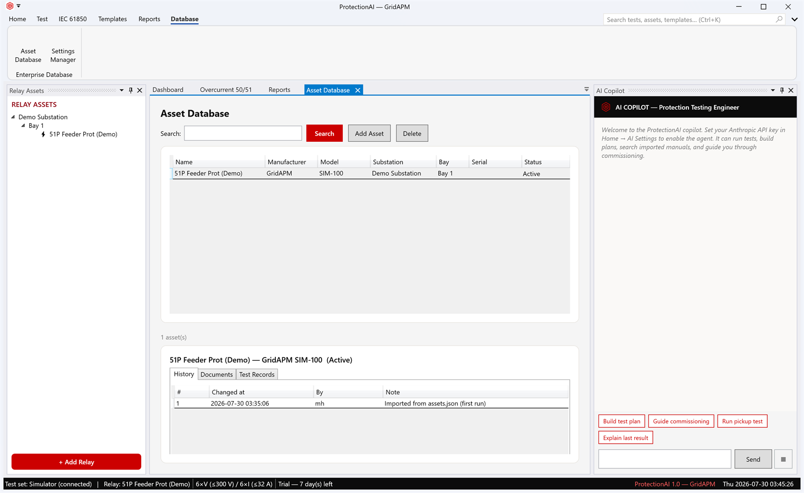
- Relay records carrying manufacturer, model, serial, substation, bay and lifecycle status, so a test result is attached to a specific device in a specific bay rather than to a filename.
- Settings versioning
- Full version history on the settings held against each asset, so as-found and as-left are two retrievable versions rather than two spreadsheets with similar names. The as-left verification gate closes only when there are no unjustified changes and every restoration item has been confirmed, which is the failure mode that leaves a relay in a test configuration.
- Attachments
- Drawings, setting sheets and PDF relay manuals attached to the asset. Ingested manuals are also what the copilot searches when you ask it a question about a specific relay.
- Test records
- Completed sessions filed against the asset, which is the raw material a maintenance-programme audit asks for. Per-asset interval tracking, due dates and exportable evidence packages ship on top of it; multi-user approval routing does not.
Records
The asset database
Output
Reporting and the copilot
- Session reports
- Measured against expected in a table, with a tolerance verdict per row, the operator recorded, and the test set named in the header — which is how the simulator stays visible in the evidence rather than quietly implied to be hardware.
- Branded export
- Word, Excel and PDF export carrying your own company logo and identity, plus CSV when the destination is a spreadsheet or another system.
- Copilot tools
- 30 registered tools: run a test, read and edit the working settings model, drive output phasors, generate or import a template, search ingested PDF manuals, draft a report, and a read-only analysis set covering failure diagnosis with ranked causes, chart explanation, COMTRADE analysis, coordination margins, settings sanity, PRC-005 status, report narrative, commissioning checklists and history trending. Consequential steps stop for your approval, and the isolation gate on every energising tool is enforced centrally rather than per handler. It streams responses, accepts attachments and takes microphone dictation.
- Your key, your provider
- The copilot needs an Anthropic, OpenAI, xAI/Grok or Google/Gemini API key that you supply. It is encrypted at rest with Windows DPAPI and used only against the provider you configured. Leave it unset and every capability above is still reachable by hand.
Honest status
Implemented, partial and roadmap
Derived from the internal capability matrix. Partial means shipping with a stated limit; roadmap means not built.
| Capability | Status in ProtectionAI today | Note |
|---|---|---|
| Manual phasor injection | Implemented | Manual Injection view against the simulator driver. |
| Pickup and dropout ramping | Implemented | Multi-segment, pulse and synchronized ramps, with the reset ratio produced by modelled element hysteresis rather than echoed from the pickup. |
| Timing tests against standard curves | Implemented | Expected times from the IEC 60255-151 and IEEE C37.112 equations. |
| Overcurrent (50/51) characteristic | Implemented | I–t sweep and plot. Directional and sequence-element variants are roadmap. |
| Distance (21) characteristic | Implemented | Mho zone boundary search in R–X plus a quadrilateral zone editor with per-loop k0 compensation. On the simulator only the three-phase loop presents the target impedance. |
| Differential (87) characteristic | Implemented | Operate-point search in the bias and differential plane, 2nd and 5th-harmonic block search, and a trip-time characteristic. The simulated harmonic block is magnitude-only. |
| Multi-state sequencer | Implemented | Prefault, fault, postfault with expected binary transitions. |
| Voltage and power elements (24, 27/59, 32, 51V) | Implemented | Dedicated modules for V/Hz, under and overvoltage, directional power and voltage-controlled overcurrent. |
| Test plans chaining modules into one report | Implemented | JSON test plans executed by the test runner. |
| COMTRADE read, plot and playback | Implemented | IEEE C37.111. Playback terminates at the simulator today. |
| XRIO and RIO settings import | Implemented | Both imported into one normalised settings model. |
| SCL import (SCD, ICD, CID) | Implemented | Reads IEDs, datasets and control blocks from the substation configuration; an SCL writer exports under a preserve-verbatim-or-refuse contract. |
| Asset and settings database | Implemented | SQLite, with lifecycle states, version history, attachments and test records. |
| Branded reporting and export | Implemented | Word, Excel, PDF and CSV, with your own logo and pass or fail verdicts. |
| Offline licensing | Implemented | 7-day trial, then RSA-signed per-machine activation with no cloud dependency. |
| AI copilot with relay-manual retrieval | Implemented | Tool-using agent with approval gates, on your own provider key. |
| Simulated relay for rehearsal | Implemented | A simulated relay and virtual test set, plus a network model with an IEC single-line editor and a scenario library. |
| Network short-circuit solver | Implemented | Symmetrical-component solver for 3ph, ph-ph, ph-g and ph-ph-g faults with fault resistance; all six distance loops with k0 compensation, plus SIR. Unit-tested against hand-computed reference cases. |
| Transient generation and closed-loop playback | Implemented | DC offset with X/R decay, CT saturation, CVT subsidence, evolving faults and inrush; the breaker opens at the next current zero and the simulation continues. |
| As-found and as-left verification gate | Implemented | Passes only with no unjustified changes and every restoration item confirmed. The settings diff states how many parameters were compared and will not report identical for a mismatched comparison. |
| Evidence-completeness scoring | Implemented | PRC-005 R3 evidence assistant with completeness scoring and one-click evidence packages. |
| Settings-driven automatic test generation | Partial | The 87T and quadrilateral-distance modules derive expected values deterministically from the imported settings model, and a Plan Generator builds a draft plan from it, writing a note for anything it cannot express. Extending expectation binding to every module is roadmap. |
| Scripting and formulas | Implemented | A test-script language with an editor and runner; every instrument command drives the active driver, and energizing commands are refused without the operator's isolation confirmation. |
| Relay-model-specific template library | Partial | 21 curated relay packs with per-parameter provenance, plus a 379-entry catalog verified for model identity only — numbers generated from a catalog entry are labelled unverified estimates. |
| GOOSE publish, monitor and mapping | Partial | Deterministic loopback plus named-NIC SharpPcap/Npcap transport, with no silent fallback between them; Npcap is a separate licensed install and live NIC/IED qualification is pending. |
| Sampled Values publishing (9-2LE) | Partial | Loopback and physical-interface transport; user-mode Windows timing is not merging-unit-grade and live qualification is pending. |
| Physical test-set control (OMICRON, Doble, Megger, ISA, SMC) | Partial | OMICRON CM Engine discovery, lock, static phasors, output control and software ramps are protocol-tested but not HIL-qualified; a generic SCPI source driver ships with no trip sensing; the other vendor drivers are stubs that refuse to connect. |
| Autoreclose (79), synchrocheck (25), 81 and ROCOF, 68 and 78 modules | Implemented | Dedicated workspaces are registered in the shipping build and use the shared deterministic result model. |
| System-based, network-model-driven testing | Implemented | Closed-loop model-driven testing against the built-in network model. This workflow remains simulator-only, and PL4 (ATP and EMTP) waveform import is still roadmap. |
| Synchronized end-to-end trigger evidence | Partial | Real NTP offset/uncertainty measurement and configurable GOOSE trigger receipts are implemented, including optional release of a capable armed driver. GPS/PTP/IRIG-B and hardware-timestamped qualification remain roadmap. |
| Sampled Values subscription and scope analysis | Partial | SV capture and decode are real over the Npcap transport, with a capture ring buffer exporting to COMTRADE; the scope-style stream analyser view is roadmap. |
| Sim and Test-flag virtual isolation workflows | Roadmap | The guided workflow is not built; live-network qualification comes first. |
| Merging-unit and process-bus testing | Roadmap | Blocked on user-mode Windows sample cadence, which merging-unit emulation requires and qualification will not change. |
| NERC PRC-005 interval tracking and evidence packages | Implemented | Per-asset programmes, editable NERC interval defaults by component type and monitoring level, Compliant/Due Soon/Overdue status, a KPI dashboard and exportable evidence packages with a manifest. Multi-user approval routing is roadmap. |
| Native vendor settings-file importers (SEL, GE, Siemens) | Partial | SEL ASCII, DIGSI 5 XML and generic name/value CSV/TXT import ship behind a content-sniffing detector; proprietary binary containers are refused rather than misread. GE, ABB PCM600, MiCOM S1, Beckwith and Basler remain roadmap. |
| Meter, transducer and power-quality testing | Roadmap | Outside the near-term scope. |
| PMU testing (IEEE C37.118) | Partial | TVE, FE and RFE are computed as the standard defines; the measured phasor is entered by hand or imported from the PMU's own export, and a case with no reported phasor is recorded not verifiable. |
| Traveling-wave and time-domain testing | Roadmap | Research stage; conventional amplifier bandwidth is the constraint. |
| Tamper-evident result sealing | Roadmap | Reports are branded and attributed, but not cryptographically sealed. |
| SCADA, EAM and historian integration | Partial for file hand-off | An Integrations module exports an .ics calendar, CMMS-import CSV in generic, Maximo or SAP PM layouts, and a pre-filled mailto draft. No vendor API connections and no stored credentials; live integration is roadmap. |
The other GridAPM product
GridAPM also builds AgenticGrid Pro
AgenticGrid Pro
A local-first transformer APM workbench: diagnostic evidence in, an engineer-signed work package out.
Try it for seven days and check the claims yourself
Install ProtectionAI on a Windows machine, import your own XRIO or RIO settings, run the plans you would really run against the built-in simulator and export a report on your own letterhead. No key is needed for the trial, and no internet connection is needed to run it. When you want a per-computer licence, email sales@gridapm.com.