Primary vs Secondary Injection Relay Testing: What Each Method Proves
A practical explanation of primary and secondary injection testing, including CT and VT circuits, relay terminals, trip paths, scheme testing, limitations, and evidence.
On this page
The phrase “the relay was tested” hides an important question: where was the test signal introduced? Primary and secondary injection are not competing labels for the same activity. They exercise different portions of the protection chain and should be selected against the engineering question.
Secondary injection: test at the relay boundary
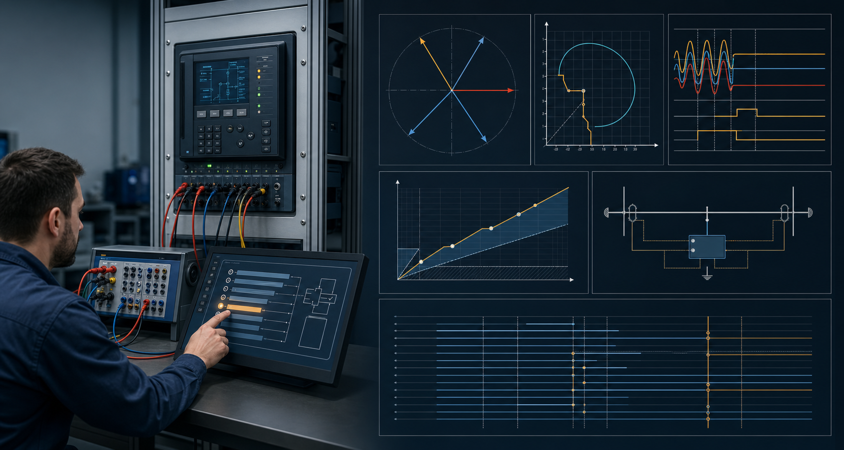
Secondary injection introduces controlled current and voltage at the relay or its test interface. It is efficient for proving relay algorithms, settings, characteristics, directional behavior, timers, logic, binary I/O, and many scheme cases. The test-set operator can vary magnitude, phase, frequency, and sequence components without applying primary current to the power circuit.
The result is meaningful only when the injection point and the rest of the circuit are identified. A clean result at relay terminals does not by itself prove:
- CT ratio and polarity in the primary circuit;
- VT ratio, phase relationship, and fuse or MCB path;
- test-switch wiring and shorting behavior;
- current-transformer burden or saturation under the relevant conditions;
- breaker trip coils, lockout, auxiliary contacts, and mechanism;
- communications-assisted or end-to-end behavior.
The correct conclusion is “the defined relay-side function passed under the stated connections,” not “the protection scheme is fully commissioned.”
Primary injection: include the installed current path
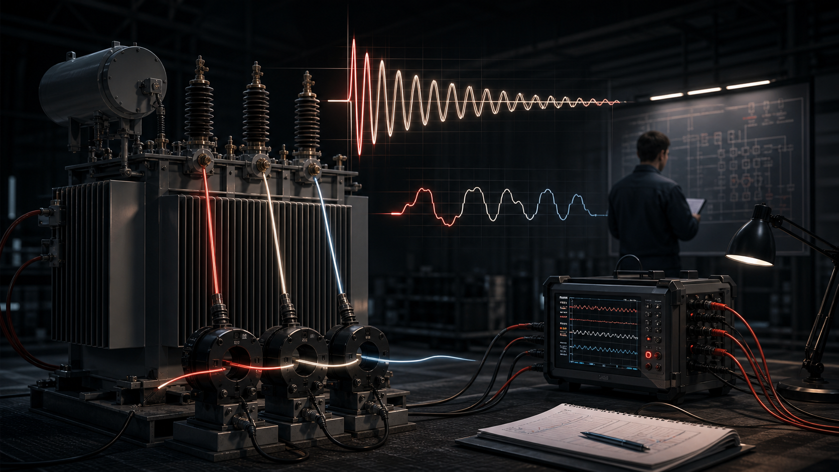
Primary injection applies current through the primary circuit or a defined primary-side path so that the installed transformers and wiring participate in the measurement. It can reveal ratio, polarity, phasing, wiring, and connection errors that are invisible when the relay is tested downstream of the CT terminals.
Primary injection is not automatically a complete scheme test either. The current magnitude, connection, source capability, safety controls, and measured part of the circuit define the coverage. Voltage circuits, logic inputs, communications, breaker paths, and protection functions outside the injected path may still require separate tests.
Choose the method by the question
Write the test question first:
- “Does the relay operate at the approved pickup and timing?” — usually a relay-side functional test.
- “Does the installed CT circuit deliver the correct magnitude and phase?” — a primary-path or circuit-verification question.
- “Does a trip command reach the lockout and breaker?” — a binary and trip-path question.
- “Does a remote permissive cause the intended line-protection behavior?” — a communications and scheme question.
- “Does the complete system respond to a fault case?” — a system or end-to-end question.
IEEE guidance separates testing phases and methods for precisely this reason. A test method is credible when it is tied to the function and evidence it was intended to prove.
Keep the safe boundary visible
Primary injection can involve substantial energy and changes to a live or potentially live circuit. The approved switching, isolation, grounding, test-switch, and operating procedures take precedence over a generic article. Secondary injection still requires correct isolation and shorting arrangements; treating it as harmless is unsafe.
Record the connection diagram, source settings, measurement point, instrument identity, expected result, measured result, and restoration state. If the method cannot safely exercise a required behavior, mark the gap and select another controlled test.
Combine methods without duplicating paperwork
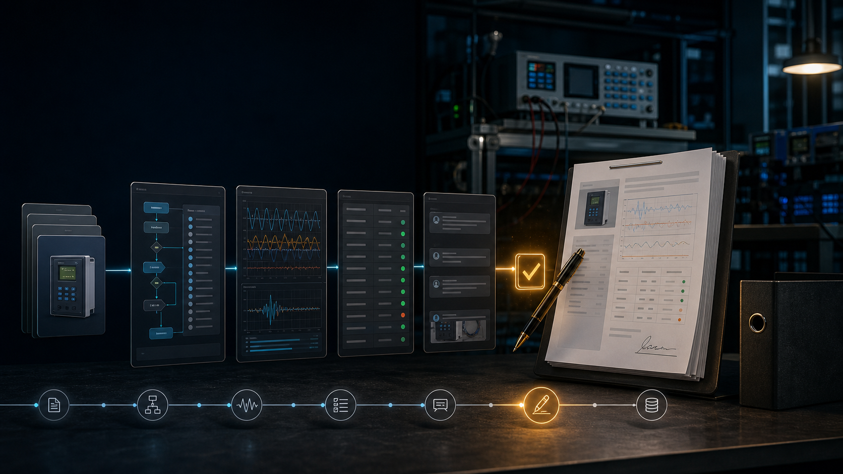
A commissioning package can contain a primary-path section, relay functional section, scheme section, and trip-path section. Link them to the same asset and settings version. Do not make technicians re-enter the same identity information in disconnected forms; use a shared evidence record and preserve the raw files from each method.
ProtectionAI can help draft the method matrix and flag a conclusion that exceeds the test boundary. It should not infer that a primary or secondary result proves an untested part of the scheme. The named engineer accepts the scope and the final evidence.
References
- Institute of Electrical and Electronics Engineers. (n.d.). Relay testing. IEEE TechRxiv topic page. https://technav.ieee.org/topic/relay-testing/
- Institute of Electrical and Electronics Engineers. (2023). IEEE guide for power system protection testing (IEEE Std C37.233-2023). https://standards.ieee.org/ieee/C37.233/6676/
- IEEE Power & Energy Society. (n.d.). Relaying performance testing. https://resourcecenter.ieee-pes.org/publications/technical-reports/pestr4
- CIGRE Working Group B5.45. (2015). Acceptance, commissioning and field testing techniques for protection and automation systems (Technical Brochure No. 637). https://www.e-cigre.org/publications/detail/637-acceptance-commissioning-and-field-testing-techniques-for-protection-and-automation-systems.html
- Pacific Power. (2018). Relay testing and commissioning checklist. https://www.pacificorp.com/content/dam/pcorp/documents/en/pacificorp/suppliers/rfps/2018ocs-rfp-docs-and-appendices/A7.16_Relay_Testing_and_Commissioning_Checklist.pdf
References
Questions engineers ask
Is secondary injection enough for relay commissioning?
It may be appropriate for many relay function tests, but it does not automatically prove CT and VT primary circuits, polarity at the source, burden, wiring through test switches, or every downstream trip-path behavior.
What does primary injection prove?
Primary injection can exercise the installed primary or transformer-derived current path and help prove ratio, polarity, wiring, and relay measurement together. The exact coverage depends on the connection and procedure.
Can primary and secondary injection be replaced by simulation?
Simulation is valuable for planning, training, and system cases, but it does not replace the physical checks required by the approved commissioning and maintenance procedure.