CT and VT Commissioning Checklist: Ratio, Polarity, Burden, Phasing, and Evidence
A practical CT and VT commissioning checklist for protection engineers, covering identity, ratio, polarity, burden, phasing, grounding, secondary circuits, and relay-side verification.

On this page
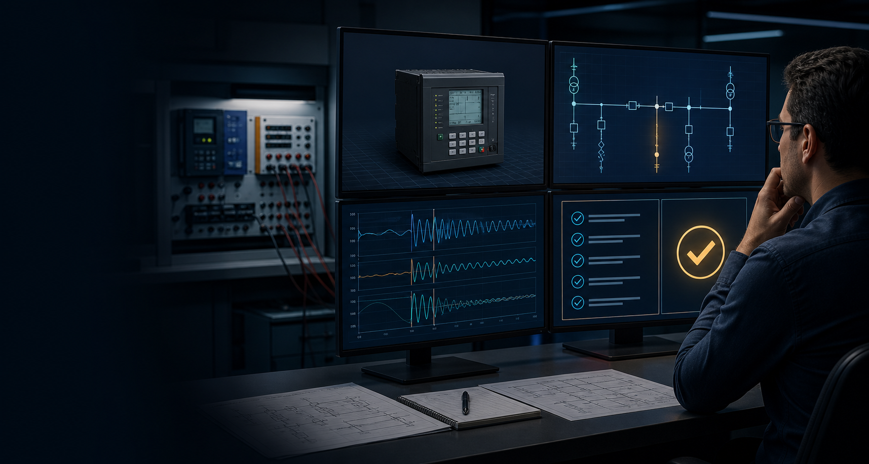
The relay is only as trustworthy as the measurement chain feeding it. A secondary-injection result can be clean while a CT polarity is reversed, a VT phase is misplaced, a test switch is wired incorrectly, or a burden is higher than the design assumed. A CT and VT commissioning checklist makes those boundaries explicit.
Establish the instrument-transformer identity
Match the nameplate, drawings, terminal markings, ratio taps, core, class, burden, polarity notation, and circuit designation to the approved design. Record the serial or asset identifier where available. A measurement can be technically correct and still belong to the wrong core or tap.
For protection work, identify whether the circuit is connected to a metering core, protection core, residual connection, summation circuit, or dedicated differential input. Capture the relay input channel and the expected phase relationship.
Verify ratio and polarity
Ratio tests should state the applied quantity, measured quantity, tap, method, and acceptance basis. Polarity should be proved by the approved method and recorded with the terminal references, not reduced to a free-text “OK.” For a differential or directional scheme, the relative polarity between circuits matters more than an isolated label.
Use a phase-by-phase record. If a result is repeated after a wiring correction, retain the as-found result and the correction. Do not overwrite the first record with the final value.
Check phasing and sequence
VT phasing and phase sequence affect directional elements, distance elements, synchronism checks, power measurements, and many control functions. Confirm the relationship at the instrument transformer, terminal block, test switch, and relay input as the procedure requires.
The expected sequence should come from the approved design, not from the assumption that every panel follows the same convention. A phase label copied from a previous bay is a common source of silent errors.
Include burden and wiring
The effective burden includes wiring, terminal blocks, test switches, fuses, and the relay or transducer input. Long runs and loose or corroded connections can change the circuit even when the relay input appears plausible at low current. CT saturation analysis should use the actual or justified loop resistance and the applicable CT class.
Record continuity, shorting behavior, grounding, insulation or resistance checks when required, and the final state of links and test switches. Never infer that a correct relay magnitude proves every part of the circuit is healthy.
Connect the result to the relay
After the circuit checks, compare the relay’s measured magnitude, phase, sequence, frequency, and quality indication with the expected values. Exercise the relevant binary inputs, alarms, supervision, and blocking conditions. For digital interfaces, record the configuration and quality behavior that carries the measurement or command.
This is where a test plan should connect physical evidence to the protection function. A CT check without a relay-side confirmation, or a relay-side check without a circuit trace, leaves an avoidable gap.
Close-out
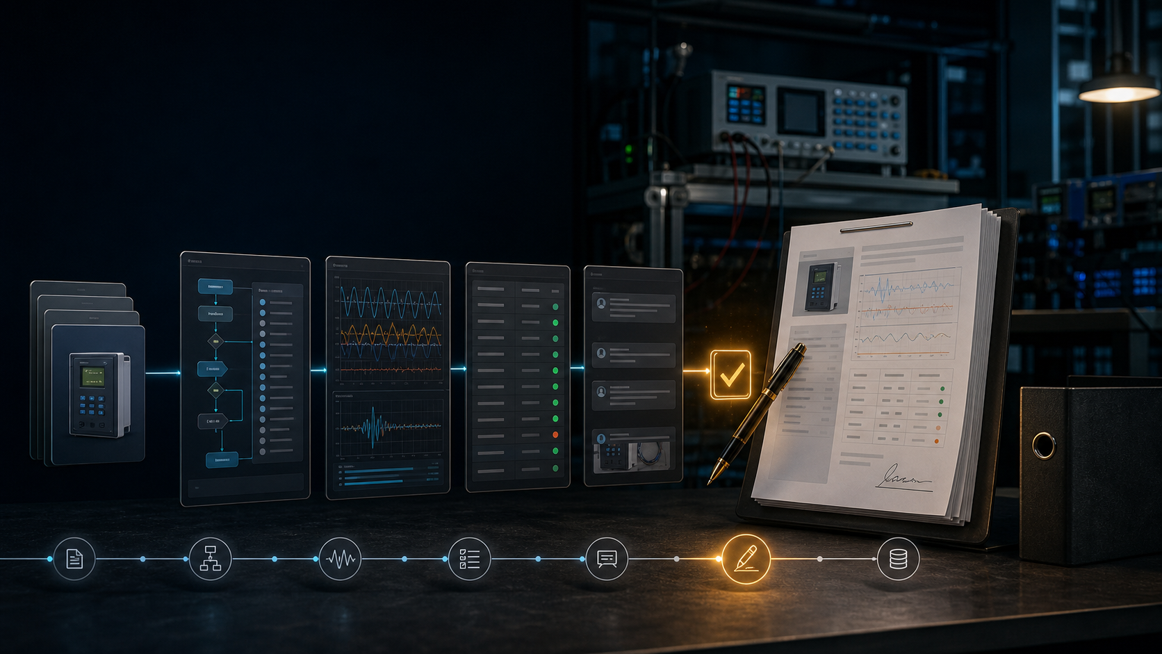
Before returning the circuit to service, verify the approved as-left state, remove temporary connections, restore grounds and links, confirm the active setting group, and record who reviewed the evidence. The measurement-chain record should travel with the relay test pack and not remain in a separate contractor spreadsheet.
ProtectionAI can help assemble the checklist, compare expected phase relationships, and surface missing fields. It cannot replace the approved switching procedure or the qualified engineer’s decision.
References
- Institute of Electrical and Electronics Engineers. (2011). IEEE guide for the application of current transformers used for protective relaying purposes (IEEE Std C37.110-2007, reaffirmed 2011). https://standards.ieee.org/ieee/C37.110/6175/
- International Electrotechnical Commission. (2012). Instrument transformers—Part 2: Additional requirements for current transformers (IEC 61869-2:2012). https://webstore.iec.ch/en/publication/6050
- International Electrotechnical Commission. (2017). Instrument transformers—Part 100: Guidance for application of current transformers in power system protection (IEC TR 61869-100:2017). https://webstore.iec.ch/en/publication/32278
- Institute of Electrical and Electronics Engineers. (2023). IEEE guide for power system protection testing (IEEE Std C37.233-2023). https://standards.ieee.org/ieee/C37.233/6676/
References
- IEEE C37.110 IEEE C37.110 — Application of Current Transformers Used for Protective Relaying Purposes
- IEC 61869-2 IEC 61869-2:2012 — Additional requirements for current transformers
- IEC TR 61869-100:2017 — Guidance for application of current transformers
- IEEE C57.13 IEEE C57.13 — Standard Requirements for Instrument Transformers
- IEEE C37.233 IEEE C37.233-2023 — Guide for Power System Protection Testing
- Pacific Power Relay Testing and Commissioning Checklist
Questions engineers ask
Why do CT and VT checks matter if the relay passes secondary injection?
Secondary injection may bypass the installed instrument transformers and much of their wiring. CT and VT checks prove the measurement chain that the relay will actually use in service.
What is the most important CT commissioning check?
There is no single universal check. Identity, ratio, polarity, phasing, burden, insulation or wiring condition, grounding, and relay-side measurements must be considered against the scheme and procedure.
Can an AI assistant approve CT polarity?
No. Software can organize measurements and flag an inconsistency, but a qualified person must verify the connection, safety controls, method, and result.