Relay Commissioning Test Plan Template: From Approved Settings to Sign-Off
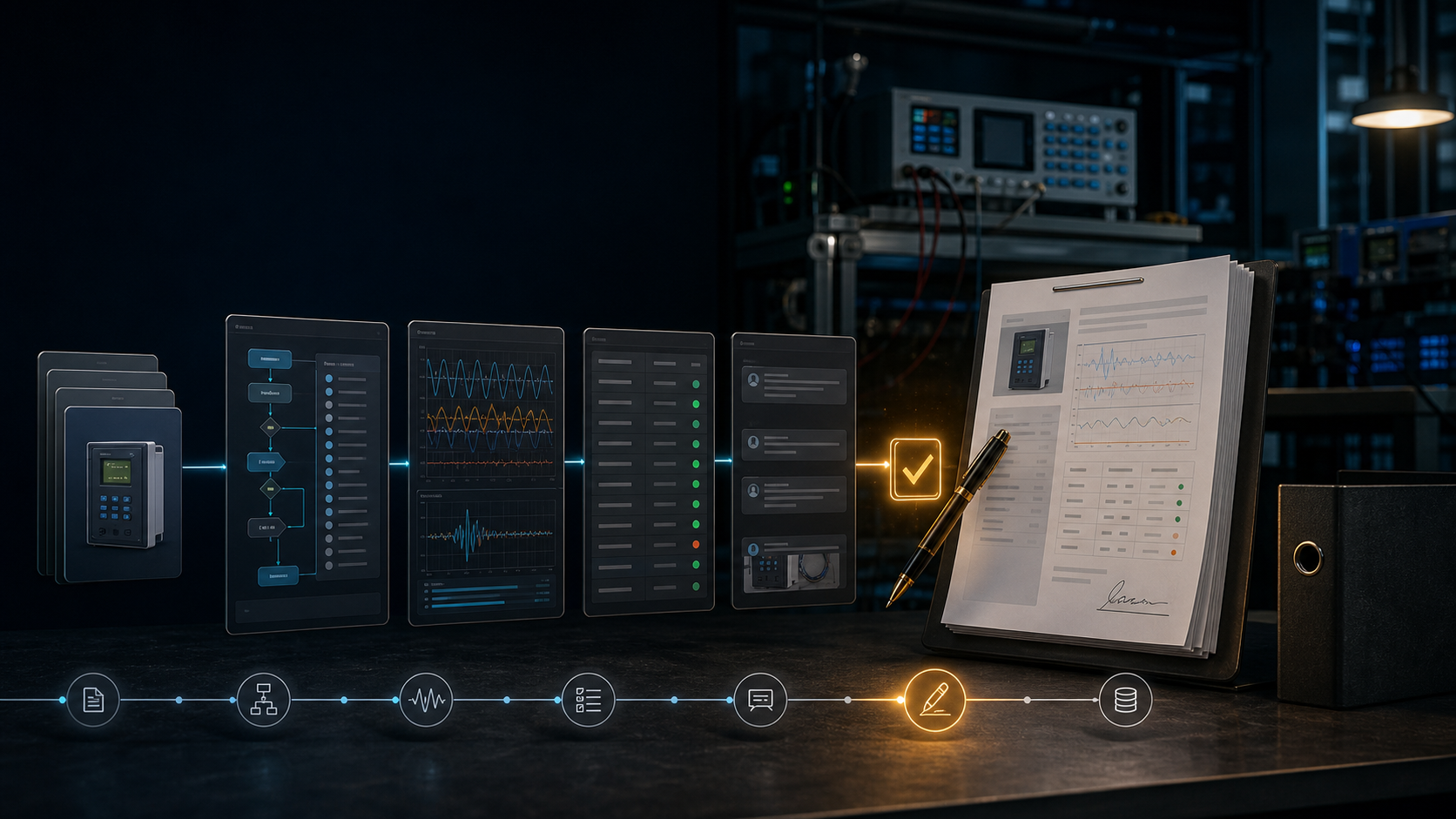
A practical structure for building a relay commissioning test plan that connects settings, logic, wiring, communications, expected results, deviations, and approval.
On this page
A relay commissioning test plan is the bridge between an approved protection design and a defensible field activity. If it only lists “overcurrent,” “trip,” and “alarm,” it is too vague to prove coverage. A reviewer needs to know which setting, input, logic condition, output, and acceptance criterion each case represents.
Begin with an identity block
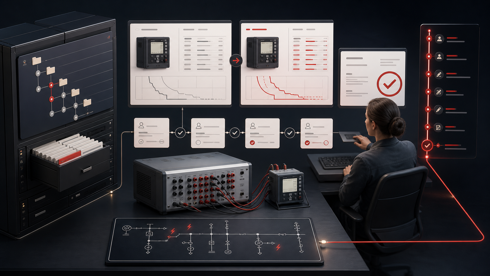
The first page should make the test impossible to confuse with another job. Include station, bay, asset identifier, relay make and model, serial, firmware, hardware revision, setting group, drawing revision, work order, test location, and test date. The identity block should link to the approved settings package and the procedure revision.
If a test plan is copied from a previous job, the identity block is the first place to detect stale context. It is not administrative overhead; it is the key that lets future engineers retrieve the correct evidence.
Define the test boundary
State whether the plan covers an element, a panel, a complete scheme, an interface, a breaker, or a system case. Then list what is outside the boundary. A plan for a relay’s distance characteristic does not silently prove teleprotection. A plan for GOOSE subscription behavior does not silently prove the breaker trip circuit.
Use a scope table with these fields:
- function or scheme behavior;
- source settings and logic reference;
- input quantities or triggering condition;
- expected output or sequence;
- test method and connection point;
- tolerance or acceptance basis;
- raw evidence required;
- reviewer and sign-off state.
Convert settings into cases
Group settings by the behavior they control. An overcurrent pickup and its time multiplier belong to a characteristic case. A directional angle belongs to forward, reverse, and boundary cases. A distance zone needs reach, angle, shape, supervision, and blocking cases. A breaker-failure timer needs the initiating trip, current supervision, timer, output, and recovery behavior.
Do not use an automatically generated point list without checking the engineering intent. Test points should exercise meaningful boundaries and failure modes, not just produce a long report.
Include wiring and binary logic
List CT and VT circuits, test switches, binary inputs, outputs, trip coils, lockout, breaker auxiliary contacts, alarms, interlocks, and communications. For each, describe the expected state and evidence. A scheme test should identify the signal path from initiating condition to final indication or trip.
For digital substations, include the relevant SCL context, GOOSE or sampled-value subscriptions, quality behavior, time source, network boundary, and packet or event evidence. IEC 61850 functional testing is a system activity; the test plan needs to show the relationship between messages and protection behavior.
Define failure handling before the test
A good plan tells the technician what to do when a point fails. Record the measured value, expected value, tolerance basis, instrument state, settings state, wiring observation, and immediate action. Preserve the as-found result even when a correction produces a pass.
The plan should have explicit states such as planned, ready, in progress, failed, repeated, accepted with deviation, rejected, and approved. Avoid a single blank “pass/fail” box that loses the investigation history.
Close with restoration
The final cases should prove the restoration state: approved settings active, correct group selected, test switches and links in service position, temporary grounds or jumpers removed, trip and close paths restored, alarms healthy, and operating authority informed. The as-left settings export belongs in the same evidence package.
ProtectionAI can draft the matrix, retrieve supporting manual sections, and highlight a setting that has no mapped case. It should present unresolved assumptions rather than inventing expected values. The engineer decides whether the plan is complete and whether a deviation can be accepted.
References
- CIGRE Working Group B5.45. (2015). Acceptance, commissioning and field testing techniques for protection and automation systems (Technical Brochure No. 637). https://www.e-cigre.org/publications/detail/637-acceptance-commissioning-and-field-testing-techniques-for-protection-and-automation-systems.html
- Institute of Electrical and Electronics Engineers. (2023). IEEE guide for power system protection testing (IEEE Std C37.233-2023). https://standards.ieee.org/ieee/C37.233/6676/
- U.S. Department of the Interior, Bureau of Reclamation. (2011). Operation, maintenance, and field test procedures for protective relays and associated circuits (FIST 3-8). https://usbr.gov/power/data/fist/fist3_8/vol3-8.pdf
- U.S. Department of the Interior, Bureau of Reclamation. (2022). Management of protective relay settings (FIST 6-4). https://www.usbr.gov/power/data/fist/FIST_6-4_%281-2022%29.pdf
References
- IEEE C37.233 IEEE C37.233-2023 — Guide for Power System Protection Testing
- IEEE PES Relaying Performance Testing
- CIGRE Technical Brochure 637 — Acceptance, commissioning, and field testing
- U.S. Bureau of Reclamation FIST 3-8 — Protective relay field test procedures
- U.S. Bureau of Reclamation FIST 6-4 — Management of protective relay settings
Questions engineers ask
What belongs in a relay test plan?
Include scope, asset identity, approved settings and drawings, test method, connections, cases, expected values, acceptance criteria, evidence requirements, restoration steps, deviations, and named review responsibilities.
Should every setting have its own test point?
Every protection and logic setting that affects the in-scope behavior should be traceable to a test, a justified grouping, or an explicit exclusion approved by the responsible engineer.
Can a test plan be generated automatically?
Software can draft a plan from structured settings and templates, but the scope, assumptions, safety controls, and final acceptance still require qualified engineering review.