Busbar Differential, Breaker Failure, and Transfer Trip Testing
A practical scheme-testing guide for busbar differential protection, breaker-failure logic, transfer trips, lockout, and restoration evidence.

On this page
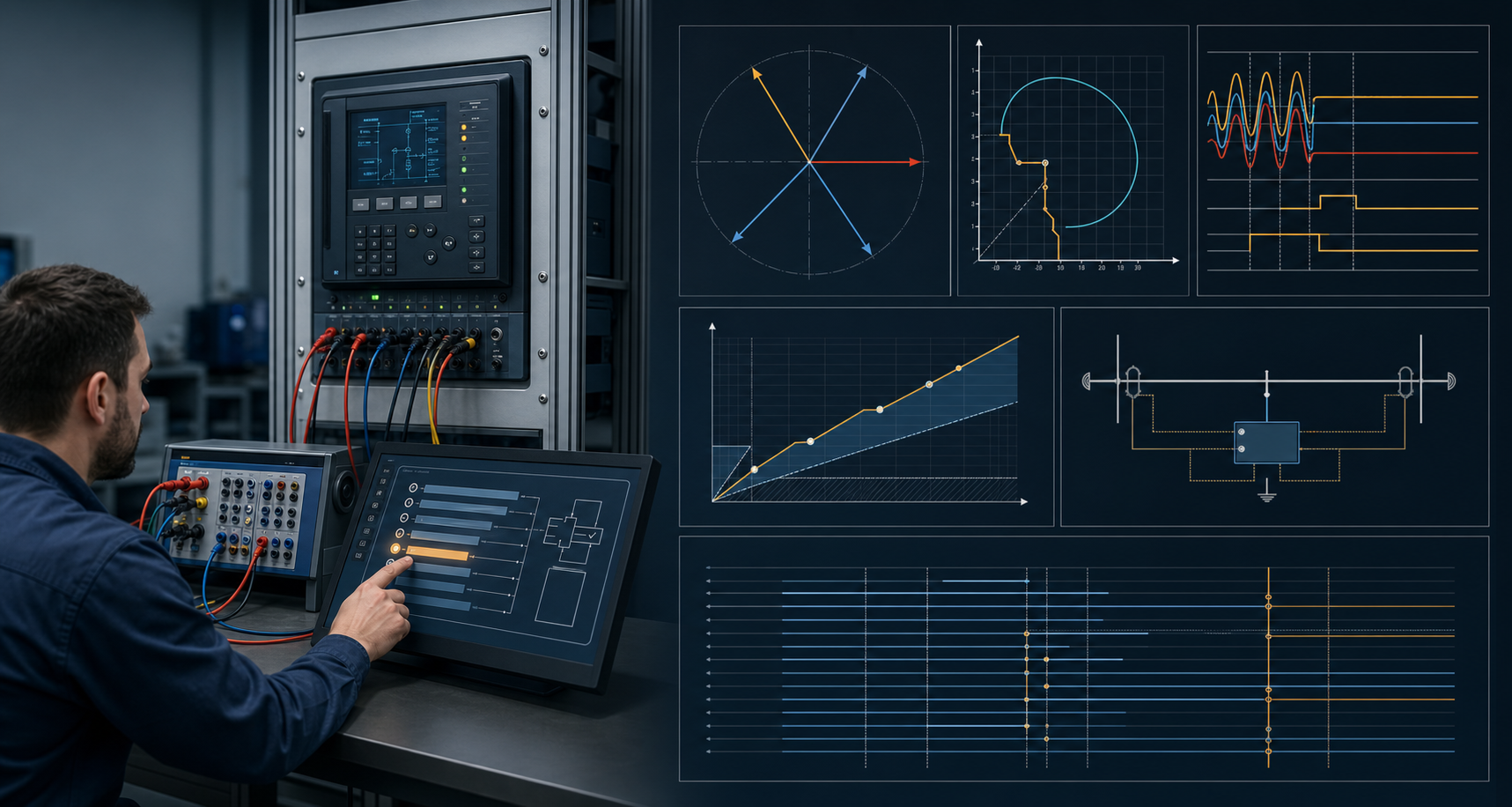
Busbar differential, breaker-failure, and transfer-trip functions are easy to under-test because they cross device and bay boundaries. An element can operate correctly while zone selection, CT mapping, breaker status, timers, lockout, or transfer logic remains wrong. The test plan should be written as a sequence of system behaviors.
Define the topology and zones
Record the bus arrangement, breakers, CT cores, isolator or disconnector status inputs, protection zones, check zones, and trip outputs. Link every current input and status signal to the approved drawing and configuration. The same relay may participate in different scheme behavior depending on the topology state.
Do not start with a generic “bus fault” case. Define which zone is faulted, which bays should trip, which bays should remain stable, and what the check or blocking logic should do.
Test stability and selectivity
Include an internal-fault case, an external or through-fault case, and topology states that challenge zone selection. Record differential and restraint quantities or the equivalent deterministic evidence, along with the intended trip or restraint decision.
For each case, prove the correct breakers operate and the non-faulted sections remain protected according to the approved scheme. A pass should identify the case and the outputs, not merely state that the relay target appeared.
Test breaker failure as a sequence
A breaker-failure case generally has an initiating trip, a current or status condition that indicates the breaker did not clear, a timer, retrip or local action, a lockout, and backup trips to surrounding breakers. Transfer-trip or remote intertripping may be part of the same response.
Record the initiation, intermediate binary states, timer basis, breaker auxiliary contacts, outputs, remote signal, and restoration. If the breaker is simulated, state the boundary and retain the simulation evidence.
Include communications and recovery
Where the scheme relies on transfer trip, permissive, blocking, or a digital message, test normal behavior, supervision, loss or degradation, and recovery as required by the design. The network or telecom result should be connected to the protection output and not stored as an unrelated ping or packet screenshot.
Close-out and review
Restore the topology simulation or physical switching state, settings group, test switches, lockout, outputs, alarms, and remote indications. Confirm that the final evidence identifies all affected bays and devices. A named protection engineer should review any accepted limitation or untested operation.
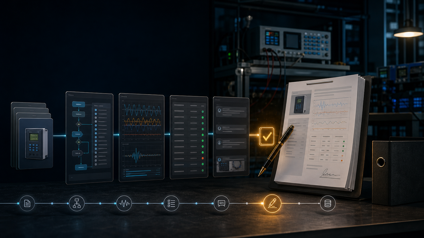
ProtectionAI can help build the case matrix from drawings, settings, and scheme records, flag a zone without a corresponding case, and assemble evidence. It should not decide which breakers are safe to operate or declare a complete station scheme tested without the physical and operational evidence.
References
- Institute of Electrical and Electronics Engineers. (2023). IEEE guide for power system protection testing (IEEE Std C37.233-2023). https://standards.ieee.org/ieee/C37.233/6676/
- IEEE Power & Energy Society. (n.d.). Relaying performance testing. https://resourcecenter.ieee-pes.org/publications/technical-reports/pestr4
- CIGRE Working Group B5.45. (2015). Acceptance, commissioning and field testing techniques for protection and automation systems (Technical Brochure No. 637). https://www.e-cigre.org/publications/detail/637-acceptance-commissioning-and-field-testing-techniques-for-protection-and-automation-systems.html
- Pacific Power. (2018). Relay testing and commissioning checklist. https://www.pacificorp.com/content/dam/pcorp/documents/en/pacificorp/suppliers/rfps/2018ocs-rfp-docs-and-appendices/A7.16_Relay_Testing_and_Commissioning_Checklist.pdf
References
Questions engineers ask
Why is a busbar differential test different from an element test?
The scheme depends on zone selection, CT inputs, isolator status, restraint or stability behavior, outputs, lockout, and breaker interfaces. The system behavior cannot be reduced to one relay pickup point.
What should a breaker-failure test include?
The approved scope should define initiation, current or breaker-status supervision, timer behavior, retrip, lockout, backup trips, transfer signals, alarms, and restoration.
Can a simulated trip prove the station will clear the fault?
It can prove the defined simulated case within its boundary. Physical wiring, breaker operation, communications, and operating controls require the evidence specified by the commissioning procedure.