Trip Circuit and Breaker Functional Testing: From Relay Output to Verified Operation
A practical guide to testing the protection trip path, including relay outputs, lockout, breaker coils, auxiliary contacts, interlocks, alarms, SCADA, and restoration.

On this page
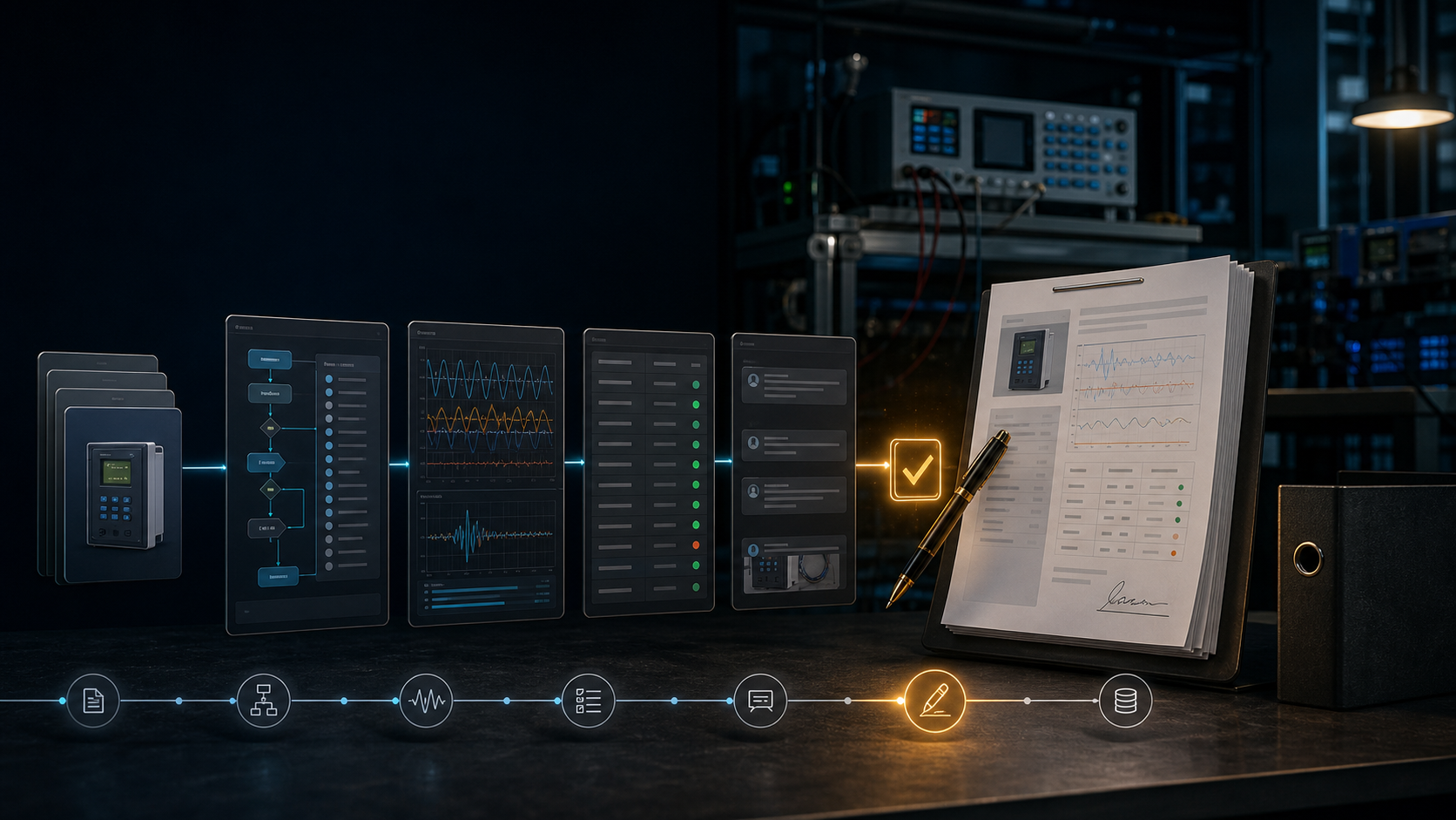
Protection testing often stops at the relay output contact. The protection system does not stop there. A trip command may pass through a lockout relay, interposing relay, test switch, breaker trip coil, mechanism, auxiliary contact, alarm circuit, and SCADA indication before the operating team sees the result.
Define the trip path
Start with the approved schematic and identify every component between protection decision and breaker state. Include the DC source and supervision, relay outputs, interposing devices, lockout, test switches, trip coils, breaker mechanism, 52a and 52b contacts, interlocks, local and remote indications, and communications.
For each path, record the initiating condition, expected sequence, operated contacts, voltage or current measurement where required, breaker state, alarm, and recovery state. A simple relay-contact check should not be labelled a complete trip test.
Check the inputs that create the trip
Before proving the output, verify that the initiating test case is valid. Confirm current and voltage quantities, settings group, binary inputs, blocking or permissive conditions, and any communication signal. The test should distinguish an intentional local trip from a remote or scheme-assisted trip.
For breaker failure, autoreclose, transfer trip, and busbar schemes, the time sequence and supervision logic are part of the function. Document the case as a system behavior rather than only as a relay element.
Verify outputs and lockout
Prove the intended relay output at the correct terminal, then follow the signal through the interposing and lockout logic under the approved procedure. Check that the correct breaker or device is addressed and that unintended outputs remain inactive. Where the scheme uses duplicate trip paths, test each path and record the result separately.
The evidence should show the contact or binary transition, the measurement or event time, the lockout state, and the reset or restoration action. If a test uses a simulated load or disconnected coil, label that boundary clearly.
Test the breaker interface
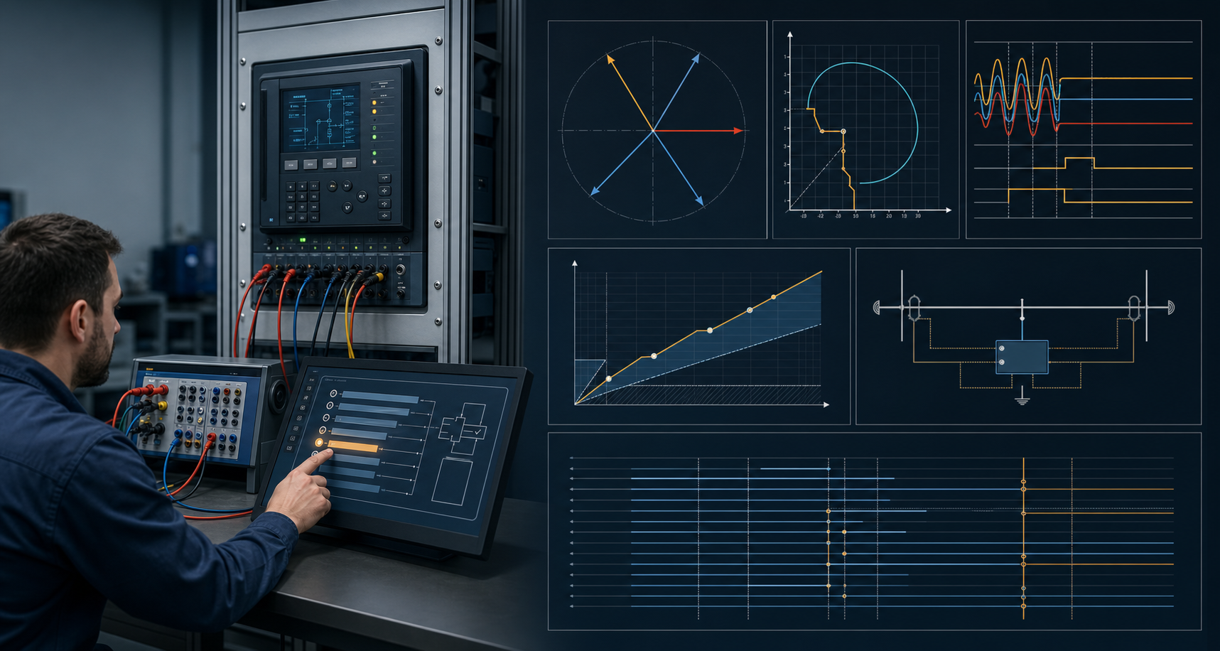
The actual breaker test should follow the station procedure and safety authority. Where included in scope, record trip-coil response, breaker movement or timing evidence, auxiliary-contact transition, DC supervision, anti-pumping, interlocks, and local/remote indications. A relay test set cannot substitute for a mechanical inspection or a breaker-maintenance procedure.
If the breaker cannot be operated during a particular stage, create an explicit alternative evidence path and an open action. Do not convert a simulated result into a claim of physical operation.
Restore and review
After the test, verify the correct state of lockout, test switches, links, trip and close circuits, active settings, alarms, and remote indications. Retain the as-found and as-left state, including any temporary wiring or bypass used during testing.
ProtectionAI can map a relay output to the associated schematic references, identify a missing output or alarm case, and draft a traceable report. It should not authorize operation or declare the trip path healthy without the physical evidence required by the procedure.
References
- Institute of Electrical and Electronics Engineers. (2023). IEEE guide for power system protection testing (IEEE Std C37.233-2023). https://standards.ieee.org/ieee/C37.233/6676/
- Institute of Electrical and Electronics Engineers. (n.d.). Relay testing. IEEE TechRxiv topic page. https://technav.ieee.org/topic/relay-testing/
- CIGRE Working Group B5.45. (2015). Acceptance, commissioning and field testing techniques for protection and automation systems (Technical Brochure No. 637). https://www.e-cigre.org/publications/detail/637-acceptance-commissioning-and-field-testing-techniques-for-protection-and-automation-systems.html
- Pacific Power. (2018). Relay testing and commissioning checklist. https://www.pacificorp.com/content/dam/pcorp/documents/en/pacificorp/suppliers/rfps/2018ocs-rfp-docs-and-appendices/A7.16_Relay_Testing_and_Commissioning_Checklist.pdf
References
Questions engineers ask
Does a relay output test prove the breaker will trip?
No. It proves the defined relay output or contact response. The complete path still includes wiring, lockout, trip coil, breaker mechanism, auxiliary contacts, DC supply, interlocks, and the required indications.
Should breaker operation be included in a relay commissioning test?
The approved commissioning scope should identify which trip-path and breaker functions must be proved, under the station safety and operating procedure. Do not operate equipment solely because a generic checklist says to do so.
Can ProtectionAI operate the breaker?
No. ProtectionAI can help map the trip logic and organize evidence, but physical breaker operation remains a controlled field activity.